
| Ergun Home Page |
| Ergun Environment |
| Ergun for Bubbling Beds |
|
| Ergun BoilersCONTACT |
Uteam-Divergent S.A.
|
Ergun CFB Software
![]() Pressure Chart
Pressure Chart
Once the physical characteristics of the CFB (solid concentrations, pressure drops, etc.) are known a "Pressure Char" can be established. Pressures at diverse levels of the loop are plotted as a function of CFB height.
The figure beside shows an example of pressure diagram plotted by the software. Once familiar with this diagram, it is simple to study where are the most important pressure drops of process. However, the main interest of the "Pressure Chart" is that one can visually check if the siphon (or the non-mechanical valve) produces enough pressure drop to prevent back-shifting from the bed to the return leg (stand pipe). Remember that such a phenomenon may cause flooding of the recirculating system.
Main pressure drops reported by the program are:
- Lower dense bed
- Secondary air level
- Tertiary air level
- Upper bed weight
- Cyclone pressure drop
- Siphon or valve pressure drop
The new version CFB1.3 provides the possibility of configuring the loop seal system by choosing between numerous options like: secondary and/or tertiary air injection, loop seal with siphon or non-mechanical valves.
Ergun Design Technology
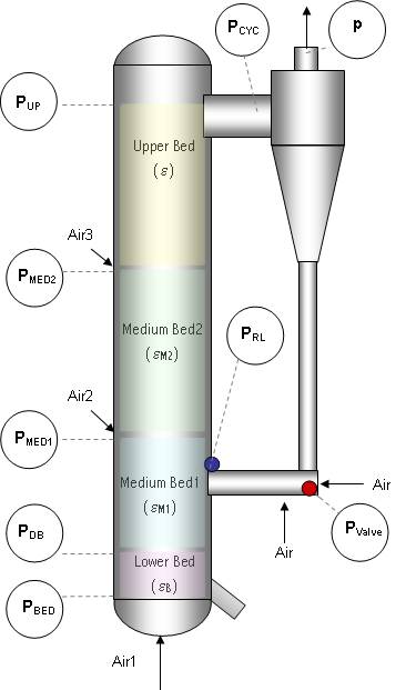
![]() Visual interface of CFB1.3 with the possibility of combining diverse options
Visual interface of CFB1.3 with the possibility of combining diverse options
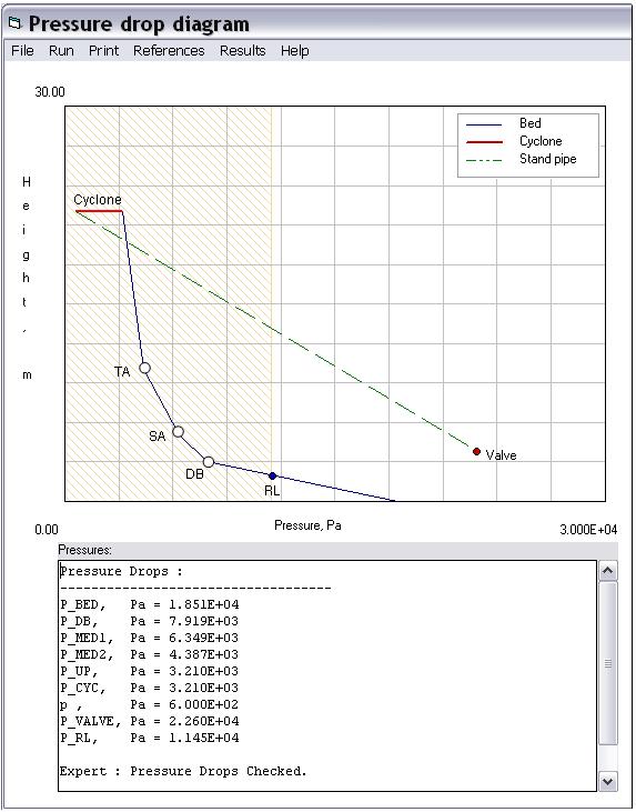
![]() Results and "Expert Comment" presented with the Pressure Chart
Results and "Expert Comment" presented with the Pressure Chart
Links to other pages: Site Map