During my professional internship, I worked
as a biomedical engineer at the biomedical department of the KMA Corporation.
There I had the chance to experience the professional life in the United States
of America, by developing maintenance tasks, tests, controls and repairs. Our
customers were big hospitals, clinics and medical centres from different areas
of the USA. This added a quota of enthusiasm since I got to travel around USA
and see how tasks are accomplished in different ways in each medical centre.
To be able to do my work correctly on the field, I had to read regulations,
manuals and procedures that are in use in USA, which are written by agencies
with an important trajectory and they are controlled very rigorously.
The objective of these agencies is to ensure a quality of high performance
in medical devices and medical installations. Controls are carried out on the
electric part, and they concern correct calibration, lost of current or a badly
operation. The inspections are carried out regularly, and their reports are
stored in an informatics system, which contains all information concerning
the tests, including parameters, values, etc. Then, if the medical device
passes the test, a sticker with the approving mark and the date of the next
control is attached on the device. The tests are carried out using Fluke devices,
which are well known for their high quality and reliability.
These devices are sent to Fluke Biomedical periodically for their control and
calibration in order to guarantee their correct operation.
These controls are very important since there have been serious cases of burns
and deaths in hospitals. Since everyone reacts in a different way to electric
current stimulus, it is necessary to conduct such controls, in order to avoid
any kind of serious injury to patients, especially the most sensitive ones.
In the next pages all information about the agencies, norms, procedures and
forms relating to a biomedical engineer that develops his career in the United
States doing electric safety checks are reported.
Healthcare Professionals Serving Your Unique Needs
KMA Remarketing Corporation was founded in 1993 by healthcare professionals
who recognized two fundamental principles. The first is the great need for
affordable, quality medical, EMS (Emergency Medical Service) and rescue products
throughout the world. The second was the awareness of the tremendous amount
of equipment available from many sources throughout the United States and Canada.
With these necessary elements of supply and demand present, the company was
born.
KMA Remarketing Corporation Has Been Developed on the Cornerstones of Integrity,
Diligence, Cost Containment and Quality Products. The culmination of such ideals
ultimately leads to the highest levels of customer satisfaction. More importantly,
with over 10 years of combined experience as healthcare providers ourselves,
the management team at KMA Remarketing Corporation never loses its vision for
providing quality patient care. This commitment to both the professional health
care provider and the patient is what; we feel, sets KMA Remarketing Corporation
apart from all other pre-owned medical equipment and services companies.
The Biomedical Engineering Department boasts:
-A state-of-the-art facility that houses a refinishing shop -- complete with
painting and sandblasting booths and an upholstery area -- and an electrical
shop with testing, repairing and calibration stations.
-An advanced, computer-generated, interactive medical asset management system.
-A staff of skilled, highly educated and certified biomedical engineering technicians
whose work meets or exceeds the standards set forth by such professional organizations
as JCAHO, AAACH, AAMI and NFPA.
-Professional liability insurance coverage for every project.
KMA Remarketing Corporation's unique combination of modern facilities and highly
educated professional staff enables us to proudly offer you the following biomedical
engineering services:
-Equipment de-installation, removal and re-installation.
-Equipment repairs (on-site or mail-in)
-Temporary equipment replacement (during repair).
-Comprehensive service contracts or "per-diem" service work.
-Routinely scheduled preventative maintenance.
-A complete refurbished program to restore equipment to like-new condition.
-Electrical safety checks.
-Replacement parts and service/operators' manuals.
From the initial inventory and tagging of every item in your facility, to preparing
professional advertising campaigns, through aggressive marketing sales and
collection of funds, to the final stages of equipment deinstallation, crating,
removal and global shipping arrangements, KMA Remarketing Corporation manages
your project from start to finish in an organized, calm, safe and professional
manner. KMA is always working hard to generate the highest possible monetary
recovery for your assets. Issues with environmental protection agencies, unions,
insurance, security, technical deinstallations and accurate record keeping
are laid to rest by our expert staff. Our management team keeps you informed
about the project's progress every step of the way with frequent reports and
strategic meetings.
KMA Remarketing Corporation will either buy your surplus medical equipment
at fair market value -- or, provide you with a comprehensive surplus asset
management contact for your organization, which will be customized to meet
your specific needs.
Regardless of which option you choose, you can be assured that KMA Remarketing
Corporation will eliminate the hassle associated with managing the disposition
of your surplus medical assets. As logistical experts who are highly
creative in our approach to problem solving, we are reactive and sensitive
to the needs of modern medical facilities as they strive to succeed in a constantly
changing healthcare arena.
-We pay up front with certified funds.
-We are insured, and provide documentation of liability coverage for every
project.
-We are knowledgeable and experienced professionals with significant healthcare
backgrounds.
-Our courteous and efficient approach to customer service is second to none.
Products & Equipment
• Anesthesia equipment
• Beds
• Cardiology equipment
• Chiropractic equipment
• Dental Equipment
• Dialysis equipment
• Disposables/consumables
• EMS equipment
• Endoscopy equipment
• Exam room furnishings
• Home healthcare equipment
• Infusion therapy
• Laboratory equipment
• Lasers
• Maternity/infant care equipment
• Monitors/defibrillators
• Neurology equipment
• Ophthalmic equipment
• Patient room furniture
• Physical and occupational therapy equipment
• Radiology equipment
• Respiratory equipment
• Sterilization equipment
• Stretchers
• Surgical equipment
• Ultrasound equipment
• Veterinary equipment
• Waiting room furniture
Regulatory codes and accreditation standards,
as well as prudent practice, make it mandatory to maintain a well-documented
inspection and testing program to ensure that the health care facility’s
electrical distribution system and electrically-powered devices are free
from fire and shock hazards.
This paper has been compiled from currently promulgated codes and standards
and is offered as an example to establishing and maintaining electrical safety
in a health care facility.
An increased sensitivity to electrical safeguards among regulatory agency
inspectors and escalating confusion as to what constitutes a reasonable electrical
safety program are the legacy of a period of intense publicity surrounding
the “microshock hazard” issue. This paper provides relevant information and
practical help in understanding the issues and instituting the proper response
for both patients and staff. I have assimilated existing standards and responsible
common sense recommendations into a plan to achieve electrical safety without
placing an unnecessary burden on the limited resources of the health care
facility.
After several years of determined investigation, no statistical evidence
has been developed to substantiate the belief that microshock is a significant
hazard comparable to other types of electrical hazards, such as macroshock
and electrical burns, in the health care facility. Much attention has been
given, however, to the so-called “microshock hazard.” This concern was based
primarily on the realization that catheterized patients with a low-resistance
conducting pathway from outside the body into the blood vessels close to
the heart could be electrocuted by current levels that are well below the
normal levels of sensation.
Quite frequently, electrical safety programs are focused on continuous electrical
shock as the reason for its existence. However, static electric shock, electrical
fires, and electrical burns should also be considered in the design of an
electrical safety program.
There is reasonable nationwide consensus on the nature of electrical shock
in the health care facility and on acceptable test procedures and test standards.
This consensus is expressed by the ANSI/AAMI Safe current limits for electromedical
apparatus standard (ES1:1993), the National Fire Protection Association NFPA-99
standard, and the Underwriters Laboratories UL60101-1 standard.
Equipment Test Procedures
The checklists and forms used in below are intended to illustrate the
type of information that might appropriately be collected during equipment
test procedures. Individual institutions may freely modify these materials
for their use or adopt other methods of recording information, such
as use of a computerized maintenance management system (CMMS).
This section also provides guidance to those who are writing or adopting
equipment test procedures for their institutions. Note that there is
no national requirement to document any of the numerical values measured
during these procedures, but individual institutions may elect to do
so.
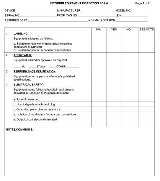
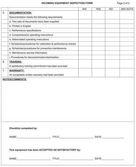
INCOMING EQUIPMENT INSPECTION
Purpose
To confirm that all electrical equipment (new or otherwise) being introduced
into patient care locations of the hospital for the first time meet
applicable standards for electrical safety.
Procedure
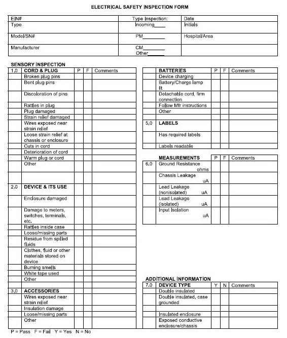
Use the Electrical Safety Inspection Form and the Incoming Equipment
Inspection Form.
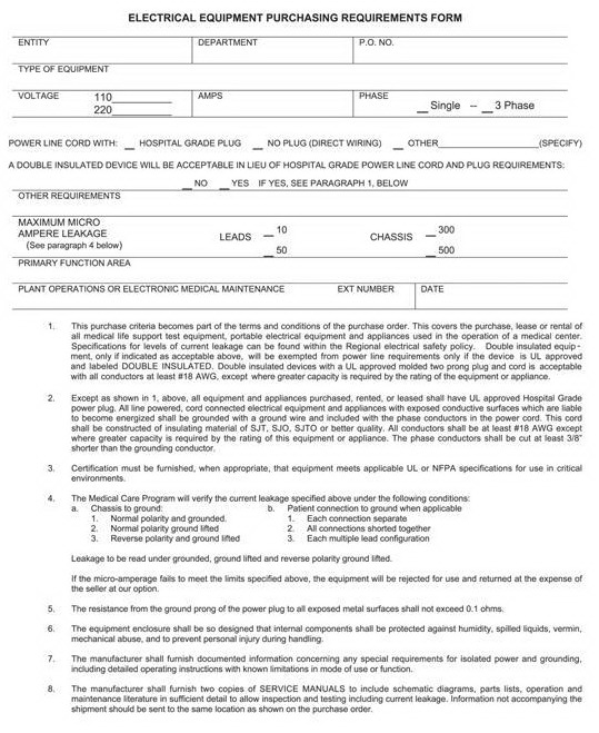
1. Confirm equipment meets all of the electrical safety requirements
specified by the health care facility on the Electrical Equipment Purchasing
Requirements Form. Note the results on the Incoming Equipment Inspection
Form.
2. Conduct applicable electrical safety test procedures described in
this area. Record results on the Electrical Safety Inspection Form.
3. Conduct any applicable functional test procedures as specified in
the health care facility’s medical equipment management plan. Record
results as specified in the plan.
4. Assign an equipment identification number as specified in the health
care facility’s medical equipment management plan. Record information
in the medical equipment inventory.
5. Perform all other tagging, labeling, documentation, and other procedures
as specified in the health care facility’s medical equipment management
plan.
NOTE—New equipment failing performance tests should be withheld from
service until remedial action has been taken. In general, problems
found should be corrected by the vendor.
RENTAL
EQUIPMENT INSPECTION
Purpose
To confirm all electrical equipment introduced into the health care
facility on a short-term basis (e.g. rental equipment) meets applicable
standards for electrical safety.
Procedure
Inspection of equipment from preferred vendors, as defined in the health
care facility’s medical equipment management plan, is not required.
Equipment from all other sources shall be tested using the Incoming
Equipment Inspection procedure defined above.
DEVICE INSPECTION AND TESTING
General Overview
The responsibility for safety testing of the facility may rest with
the facility engineer, clinical engineer, or BMET. Responsibility for
safety testing of medical devices most frequently rests with the clinical
engineer or BMET. There is an assumption that independent and appropriate
safety inspections of equipment and facility will ensure an acceptable
electrical safety level. This section will focus on the safety inspection
and testing of medical devices and equipment.
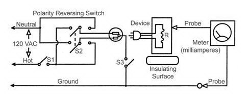
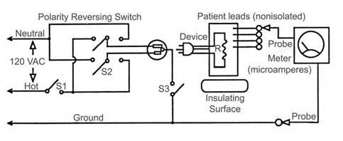
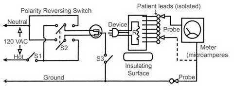
Electrical Shock Fundamentals
Understanding cause(s) of a continuous electrical shock—either macro
or micro—helps in understanding the methods for the measurement of
leakage current. The fundamental conditions that must exist before
an electrical shock can occur are two conductive surfaces must encounter
the body simultaneously. One surface must be electrified, and the second
must provide a return pathway through the body; that is, one must be
the source, and the second, the sink. The leakage current tests performed
on a device attempt to determine if the conductive surfaces can be
the source of electricity (chassis leakage or lead leakage measurements)
or a sink (isolated lead measurements). Since any grounded surface
can be a return pathway for the leakage currents, we need only determine
that, in fact, the surface is grounded.
Reasoning Behind Test Methods
Testing methods and current limits for conductive or insulated surfaces
to determine their status as either a sink or a source for leakage
currents is well described in several national standards. They are
excellent educational resources and provide the reasoning behind the
use of these methods and limits. The two most prominent are listed
below:
Safe current limits for electromedical apparatus (ANSI/AAMI ES1:1993),
available from the Association for the Advancement of Medical Instrumentation
(www.aami.org).
Health Care Facilities Handbook (7th edition), based on NFPA 99 (2002
edition), available from the National Fire Protection Association (www.nfpa.org).
Scope and Purpose
Scope
This procedure covers electrical safety inspection and testing of patient
care and nonpatient care devices and equipment. Caution: Do not make
leakage current measurements while the patient is connected to the
device.
Purpose
The purpose of this procedure is to:
• identify and use appropriate sensory inspection techniques
• ensure devices and equipment meet electrical safety standards for
leakage current and grounding; and
• ensure devices have proper labeling.
Test Equipment
• Ohmmeter (capable of accurately measuring 0 to 0.5 ohms)
• Electrical safety analyzer (or equivalent test setup).
Inspection Procedure Steps
Form
Use the Electrical Safety Inspection Form.
Record sensory inspection deficiencies.
Fundamental
Inspect extension cords following steps 1.0 and 2.0, only.
By performing the electrical safety inspection in a specific sequence,
you may detect and correct a deficiency prior to it being presented
as a hazard during the inspection.
Perform the inspection in the following order:
• Sensory Inspections
• Power Cord Ground Resistance Testing
• Chassis Leakage Current Testing
• Lead Leakage Testing
• Lead Isolation Testing
Sensory Inspections
General
With sensory inspections, you use all of your senses:
sight for broken ground pins or cuts in cords, hearing for rattles
in plugs or inside chassis, smell for detection of smoky smells or
spilled chemicals, and touch for warm cords or plugs.
NOTE—The sections below correspond to the numbered sections of the
Electrical Safety Inspection Form.
1.0 Cord and Plug Inspections
Look for:
• Broken pins
• Bent pins
• Discoloration of the pins that may suggest they have become extremely
hot, i.e. possible loose plug terminals; also consider they may have
been generated by loose terminals on the receptacle
• Loosened terminals (while holding the cord near the plug, snap the
plug “smartly” and listen for terminal rattles inside the plug that
suggest loosened terminals)
• Mechanical damage to the casing
• Broken or loosened strain relief
• Cord pulled from the strain relief and exposed wires
• Warm plug or cord (if the device has been in operation and you have
just removed it from the receptacle)
• Cuts in cords that expose inner wires
• Deterioration of the cord due to aging or chemicals
NOTE—If plugs are changed, properly rewire and test the grounding resistance
prior to putting the device back into service.
2.0 Device Enclosures and Controls and their Area of Use
Look for:
• Looseness of the cord connector (if the power cord is detachable)
when withdrawing it from the socket of the device; damage to the connector
or socket
• Obvious damage to outer casing (chassis)
• Obvious damage to terminals, meters, switches, connectors, etc.
• Unusual noises, such as a rattle inside the case
• Loose or missing parts, i.e. knobs, dials, terminals, etc.
• Residue of fluid spillage, i.e. coffee, sterilants, water, chemicals,
etc.
• Use of devices for inappropriate storage, such as fluids or clothing
• Burning or smoky smells, particularly from ventilation holes
• Notes white taped to the device that suggest device deficiencies
or operator concerns (in aprevious study, it was determined that nurses
frequently put white tape on devices for three purposes: (1) to communicate
information to other nurses; (2) to repair a device; and (3) to modify
their environment, i.e. hold stacked devices in place, hold sponge
cushions on corners of devices hung too low from the ceiling, etc.)
3.0 Accessory Inspection
Look for:
• Obvious damage to outer insulations or casings
• Loose or missing parts
• Loose screws, connections, and cables from strain relief
• Patient leads with male ends; only older accessories will have leads
with male ends (when discovered, they should be replaced with leads
that have female ends, called protected leads)
4.0 Battery Inspection
Batteries are intended to ensure the continued operation of a device
when it is not plugged into normal power. When not in use, chargers
should be plugged into a receptacle to allow charging.
• Make sure the device is plugged into a receptacle and the Charge
lamp or Battery lamp is lit. If the Charge lamp is on but the device
has not been used recently, the battery may need replacement.
• If the power cord is detachable, make sure that it is properly inserted
into its device connector.
Follow the manufacturer’s instructions for other tests, such as unplugging
the power cord, turning the device on, and operating it for several
minutes on battery and observing its function.
5.0 Label Inspection
Look for:
• readability (cleaning of devices frequently makes labels unreadable)
• assurance that all required labels are on the device (you may only
know from comparison with other or similar devices that a Caution,
Warning, or Instruction label is missing)
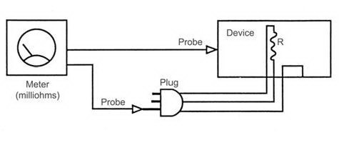
Power Cord Ground Resistance Testing
Form
Use section 6.0 of the Electrical Safety Inspection Form.
Fundamental
The receptacle grounding is carried to the device chassis through the
plug ground pin and power cord ground wire. This “safety” ground pathway
carries the normal leakage currents or any fault currents that might
be present on the chassis safely away from the operator and patient
to the earth ground.
Any breaks in this pathway may expose the operator and patient to these
electrical currents. This procedure measures the quality of one part
of the grounding pathway from plug grounding pin to the chassis.